DOWNLOAD_PDF | Colormetry-CMU-324_PLC_timing_remote signal
The analytical device Colormetry may be operated dependent on the release by a remote signal of a higher-level controller.
→ if the remote signal is ENABLED, the Colormetry proceeds monitorings in the set intervals
→ if the remote signal is DISABELED, the Colormetry switches to STAND-BY-MODE and proceeeds no analysis
If the interval time is set ZERO in the parameter settings of the Colormetry device and the remote signal is ACTIVE [release ENABLED], the Colormetry proceeds one monitoring after the other.
By CUTTING OFF the remote signal [release DISABLED] during a monitoring, this analysis will be carried out to the end and a new monitoring result will be issued.
That way, the PLC may trigger the timing of analysis intervals according to the process requirements. Colormetry becomes the slave of the PLC.
In conjunction with the converter box (optional equipment) the monitoring result will be send to the 0/4-20 mA current interface of the converter box.
IMPORTANT
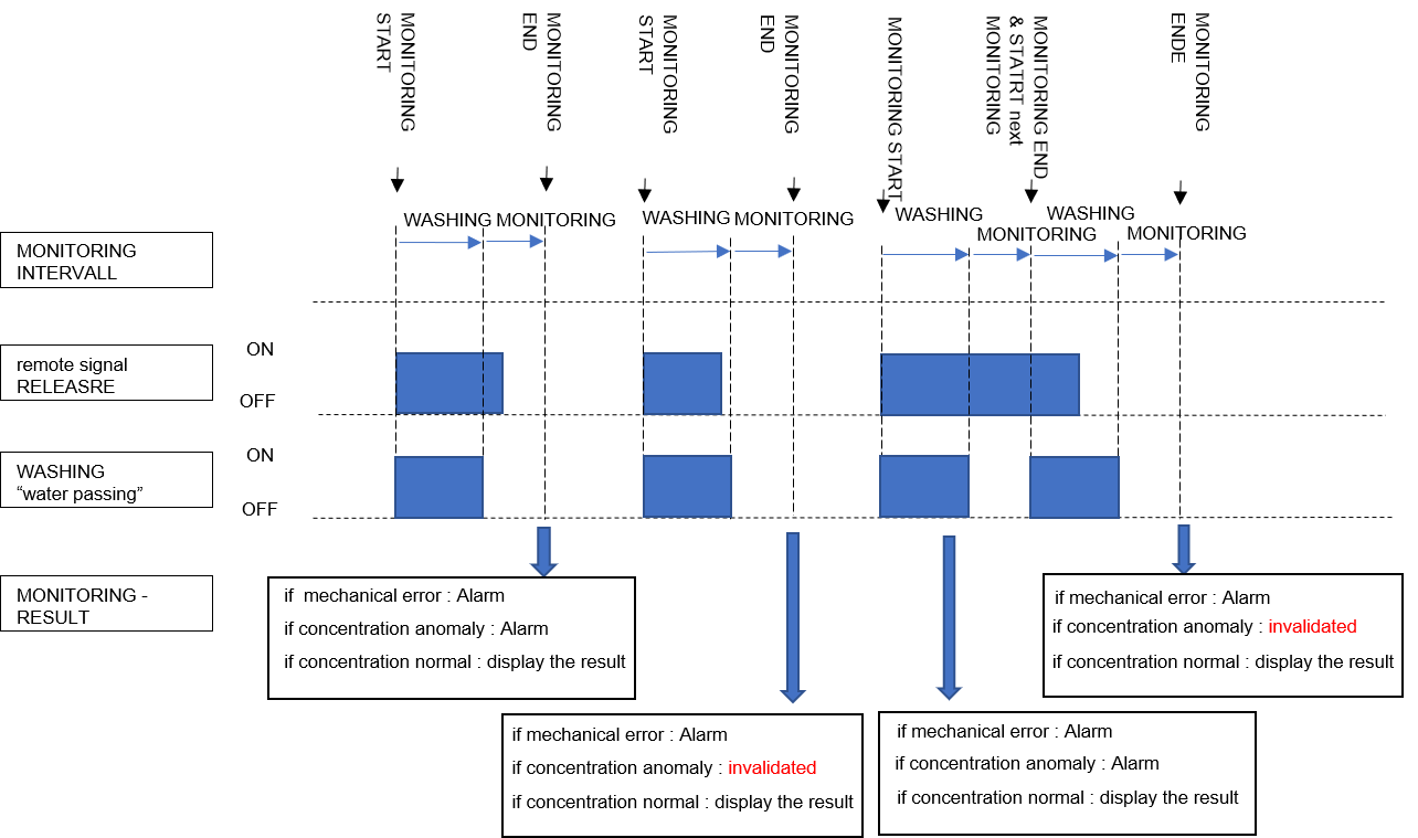
the remote signal must be ACTIVE until the end of the rinsing phase of the monitoring interval, so that the Colormetry issues a new monitoring result
⇨ please refer to the graphic below
➢ during the rinsing phase the output “water passing” on terminal clamps 5+6 of the Colormetry device is active |→ feedback to PLC
Relationship between monitoring result and remote signal
When the Colormetry starts monitoring by the request of an external remote signal, but the external remote signal is CUT OFF during the rinsing phase of an analysis interval, the result display varies depending on the monitoring result.
example ①
example ①
When concentration abnormalities are monitored (which means monitoring hard water)
Because the remote signal is interrupted during the rinsing phase and the water in the monitoring tank inside the Colormetry may be stagnant, this monitoring is invalid.
→ Result: No alarm, No communication with the conversion box | the last result is displayed in the Colormetry device
example ②
example ②
If the device error (poor chemical injection, etc.) occurs during the self-check
Because the remote signal is interrupted during the rinsing phase and the water in the monitoring tank inside the Colormetry may be stagnant, this monitoring is invalid.
→ Result: No alarm, No communication with the conversion box | the last result is displayed in the Colormetry device
example ③
example ③
When soft water of applicable range is monitored
Even though the remote signal is interrupted during the rinsing phase, if the monitored concentration is under the applicable range, this monitoring is valid.
→ Result: Monitoring result recorded, Communication On | the current monitoring result replaces the last monitoring result
COLORMETRY and CONVERTER BOX
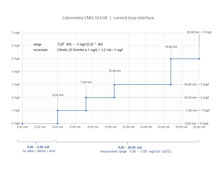
specification of the 0/4-20 mA current loop interface
The current value of the conversion box 0/4-20 mA current loop interface varies depending on the result of the Colormetry monitoring.
- if the measured value is 0mg / L [0 …0,05°dH] , the output is 4 mA
- if the measured value is 5mg / L [0,25°dH] and more , the output is 20 mA
- when no monitoring [no result] or device error occurs the output is 0 mA
converter box settings
operation mode: mode MIURA stand alone
input voltage: AC100V … AC240V (connected from outlet)
output valtage: DC24V (connected to Colormetry CMU)
terminal connector X3: connected as specified in the conversion box specification chapter 7.5.3
→ converterbox | terminal connection | colour code terminal X3
digital input X2S1-S2: for testing purposes, connect a manual switch between Signal DIO and GND
Test ① | remote signal NO TURNING OFF
Test ① | remote signall NO TURNING OFF
Self-check with hard water, automatic monitoring
NO TURNING OFF the remote signal until the end of monitoring
→ Display: 5 mg / L
→ Analog current: 20 mA
Test ② | remote signal TURN OFF
Test ② | remote signal TURN OFF
Self-check with hard water, automatic monitoring
TURN OFF the remote signal immediately after start monitoring *)
→ Display: Previous monitoring result
→ Analog current: Previous output value
*) Monitoring is invalid, No record, No communication