 |
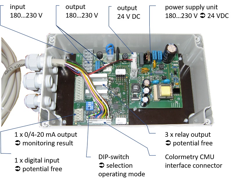
The Konverterbox is an optional equipment. |
|
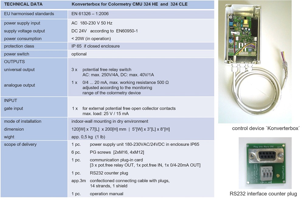
The Konverterbox is a power supply unit with transducer function. |
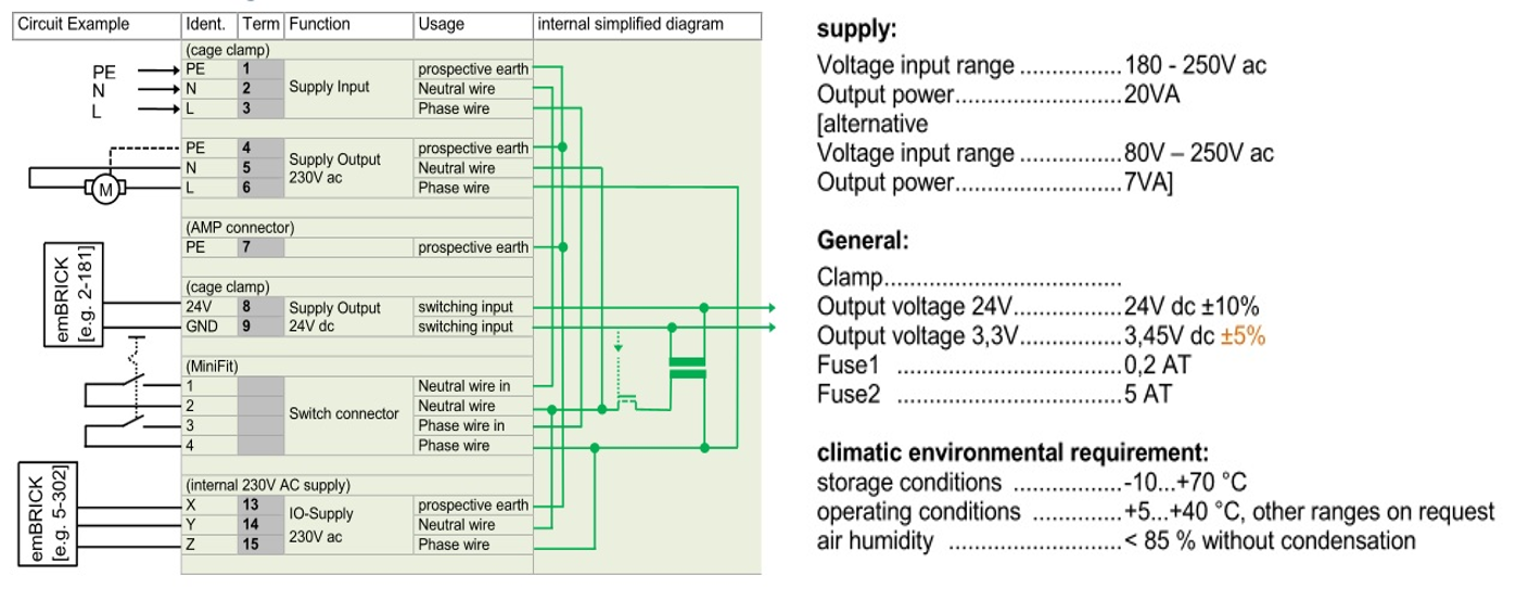
Konverterbox | Transducer Function
Konverterbox | Transducer Function
|
The Konverterbox is a power supply unit wit transducer functions |
 |
|
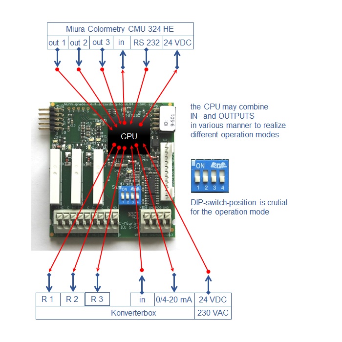
The Konverterbox transforms a |
|
|
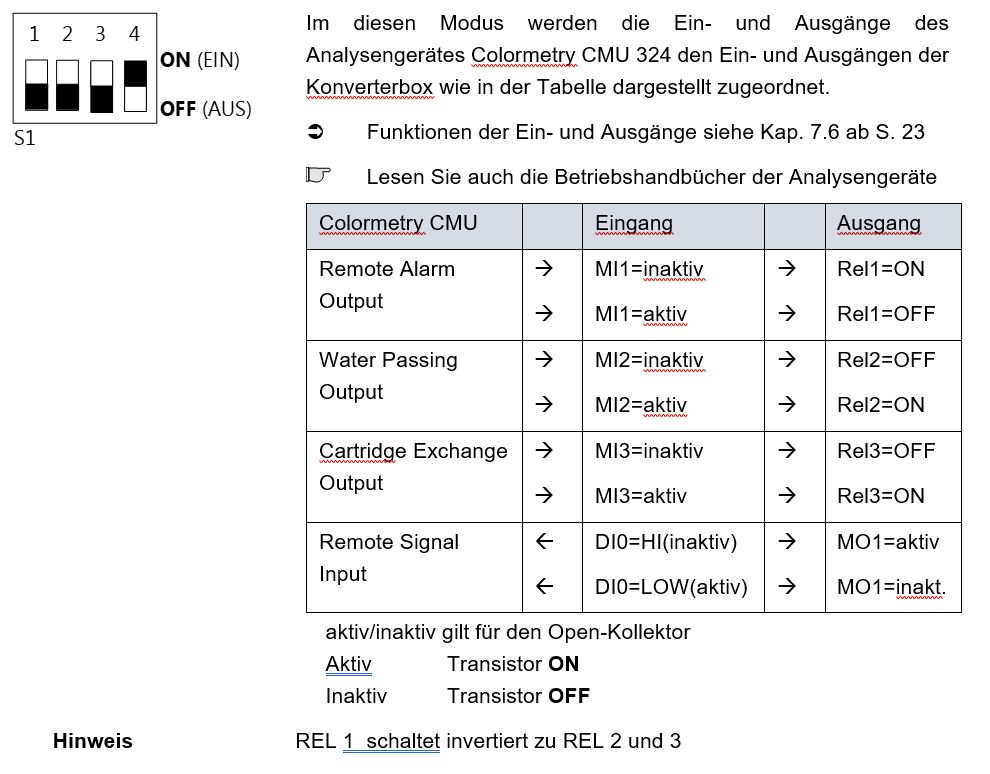
The three open collector outputs of the |
|
| A non-configurable firmware transforms the serial RS232 output signal to a currrent output signal 0/4-20 mA. |
|
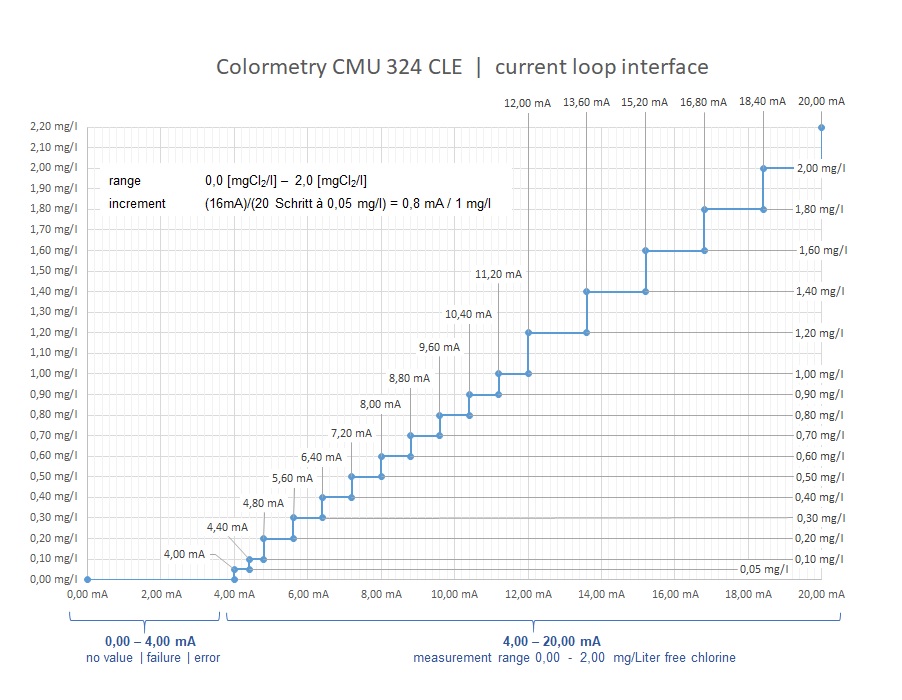
| The signal range 0-4 mA is used to transmit device failures |
|
| The monitoring result information is spread over the signal range 4-20 mA. The internal device memmory is read out clock-controlled and the most recent result is output via the current interface. |
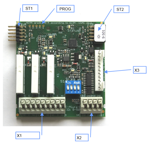
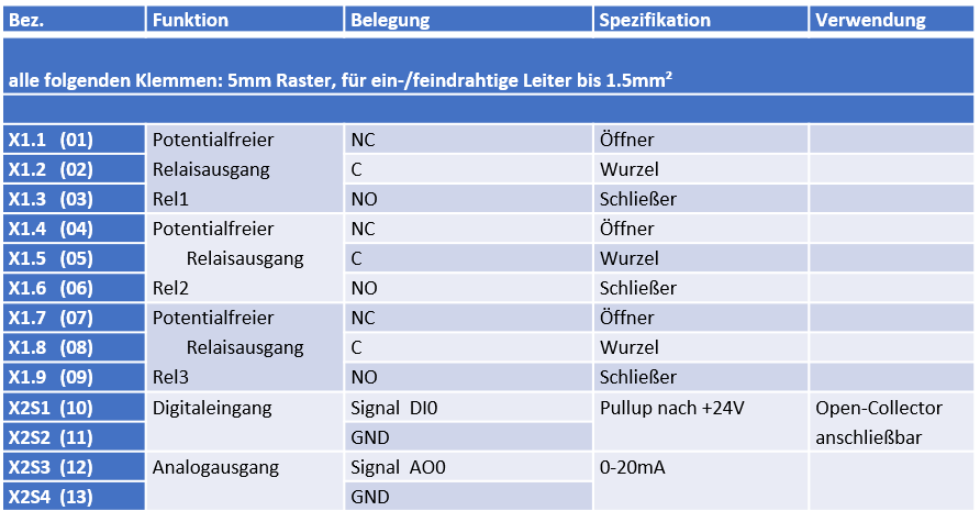
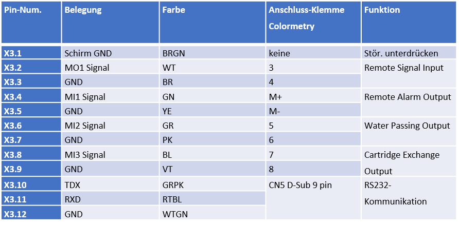
Terminal Assignments | Colour Codes of Cabeles
click here to open Click to collapse
.png)
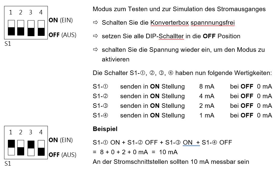
► Vor dem Einschalten wählen Sie einen Modus aus, in dem Sie die Konverterbox betreiben möchten
► Die Modus-Auswahl erfolgt über den DIP-Schalter auf der Platine (Details siehe Handbuch Konverterbox)
► Für den Betrieb der Konverterbox mit dem Colormetry ist der MODUS_1 als Standardmodus gesetzt
.png) |
Nach dem Einschalten kann der Modus nicht verändert werden.Möchten Sie den Modus ändern, schalten Sie das Gerät spannungsfrei. Dann ändern Sie die DIP-Schalterstellungen und schalten Sie das Gerät wieder ein. Das Gerät wird dann neu initialisiert und der geänderte Modus wird übernommen. |
Konverterbox | Colormetry CMU 324 | Stand-By-Function
Konverterbox | Colormetry CMU 324 | Stand-By-Function
An der Stelle „remote signal input“ muss man aus Sicht der übergeordneten Schaltwarte nachdenken, wie die Verdrahtung und die Parametereinstellung logisch richtig zueinander passen.
Bei Verwendung der Konverterbox und kompletter Verdrahtung sollte man den Parameter „remote signal input“ im Colormetry auf ON setzten und – wenn kein Schalter von außen betätigt wird – die Kontakte 3 und 4 am Colormetry brücken. Ansonsten steht das Gerät in Stand-By und führt keine Analysen aus.
Zum Test Analysenintervall im Menü auf NULL setzten, dann führt das Gerät eine Analyse nach der anderen aus, ohne einen Messwert auszugeben.
→ Über die Kabel-Brücke kann man den Schalter simulieren und das Gerät in STAND-BY setzen. Dann wird die angefangene Analyse noch zu Ende geführt und auch der Messwert ausgegeben.
→ Diese Funktionalität kann man auch nutzen, um über eine externe Master-Steuerung gezielt eine Analyse auszulösen und eine Messergebnis abzufragen.
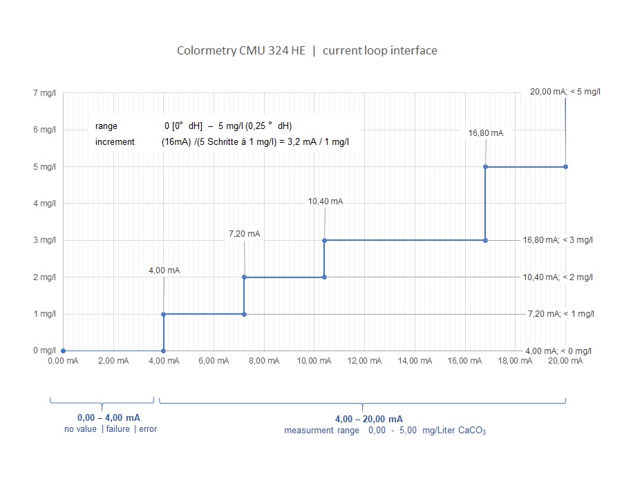
Konverterbox | current loop interface
Konverterbox | current loop interface
|
The serial output signal of the Colormetry is transformed in the Konverterbox to an analogue current output signal 0/4-20 mA. |
|
|
The signal range 0-4 mA is used to transmit device failures. The monitoring information is spread over the signal range 4-20 mA. The internal device memory is read out clock-controlled and the most recent result is output via the current interface. The signal is transmitted via the supplied RS232 counterpart board. |
|
|
|
.png)
Konverterbox | 0/4-20 mA table of values | water hardness
Konverterbox | 0/4-20 mA table of values water hardness
Konverterbox | 0/4-20 mA table of values | free chlorine
Konverterbox | 0/4-20 mA table of values | free chlorine